It seems I have just built the world’s first open source switch ASIC and I am getting it back from the fab mid november.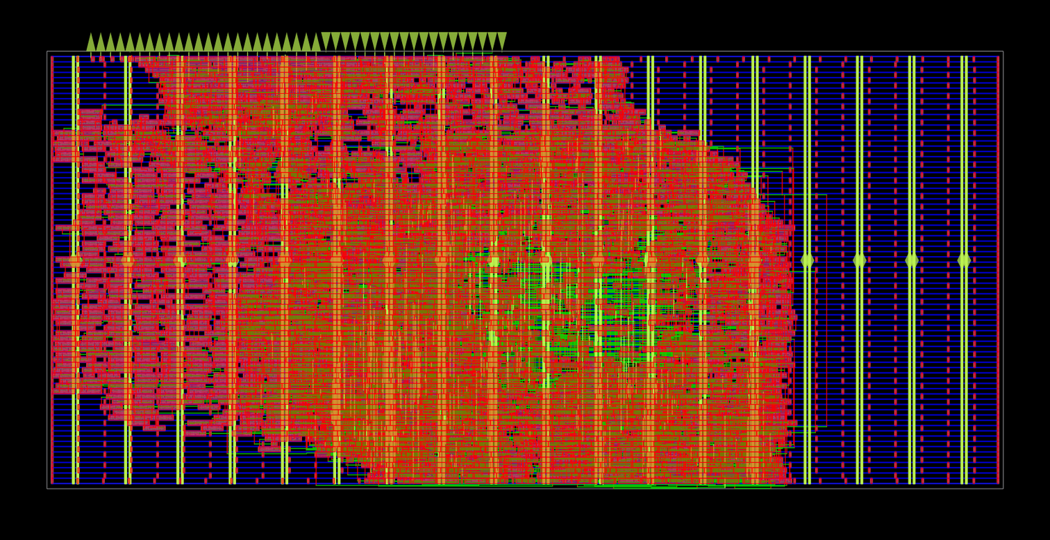
711.2 x 325um of area. The first version of this chip is currently taped out on the Tiny Tapeout gf26b shuttle chip, part of the second wafer.space run. Silicon bring-up is expected to start 2026-11-15.
Here is its repository :
Buckle up and welcome to the tale of more madness.
Where are the open source networking ASICs?#
Recent FCC decisions have put the central importance of networking equipment top of mind, and in doing so, have also put the total absence of any entirely open source networking equipment hardware at the top of my mind.
Although Open Source Silicon is in its infancy we are currently seeing a number of projects being designed, tested, and for the most ambitious ones, even taped-out with some proven silicon already in the wild.
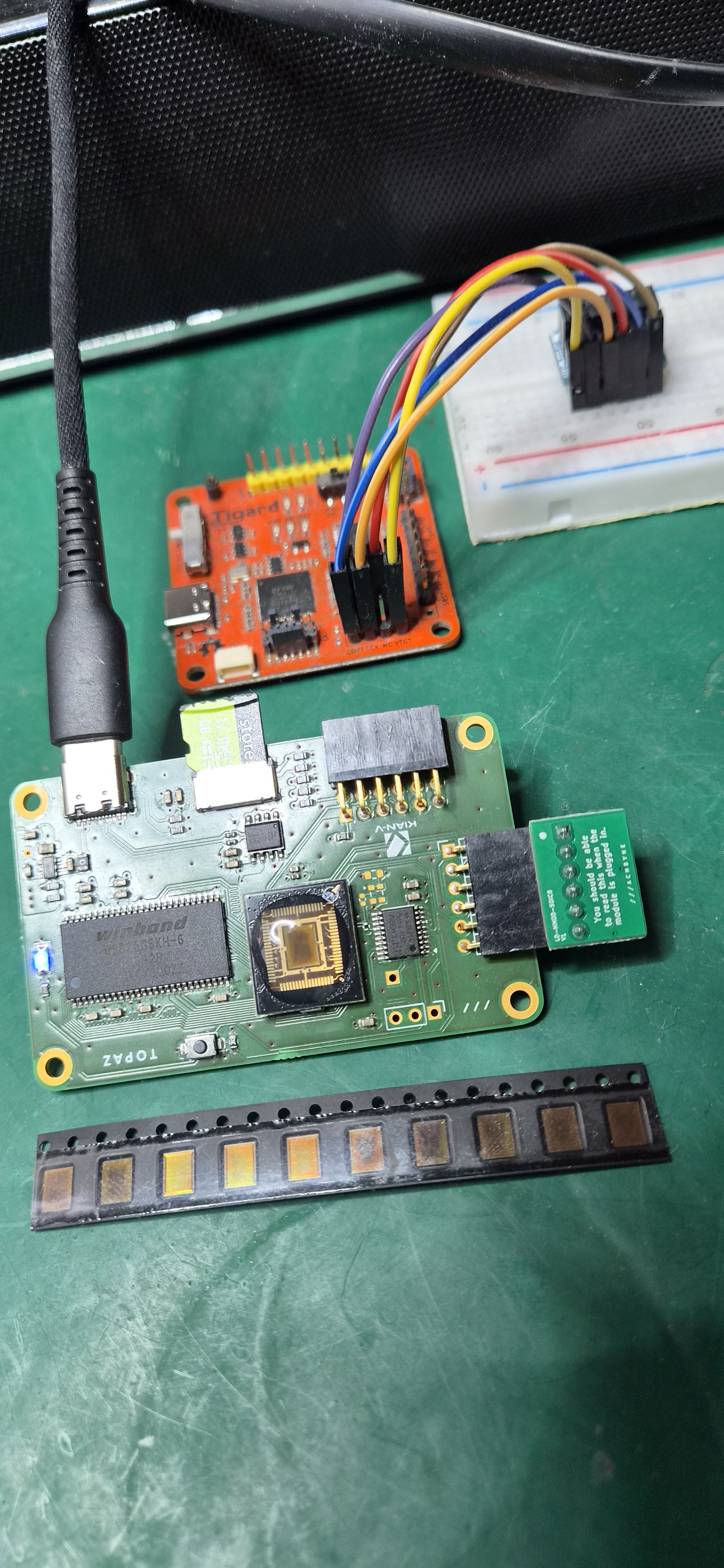
That said, the vast majority of the most ambitious projects are predominantly RISC-V SoCs.
Surprisingly, there has been much less interest in building open hardware for networking equipment.
Well .. unsurprisingly actually … networking equipment is far less “sexy” than CPUs and has thus received much less attention from the open source community. On the other hand, this means there’s a huge untaped boulevard of projects open to anyone with more time than common sense to build open source networking equipment chips!
Because, on the other side of the great silicon divide, the world of open source networking equipment is actually quite rich, both in terms of its flourishing software ecosystem and the open PCB/electronics ecosystem, with a flurry of fully featured open source routers available. Yet, due to the current ecosystem’s limitations, under the hood, these are all still all running closed-sourced, blackbox proprietary chips for the central compute and routing tasks.
So what would it take to build a router chip?
It’s a very ambitious project, since a router involves a complex SoC needing both a powerful enough CPU to run the networking stack alongside specialized networking hardware, and analog frontends for the wired and wireless connections. Since building a full router outright is much too ambitious of a greenfield project for a single person to ever hope to pull off, let’s begin with a more approachable first step: building a switch. After all, although most people only have one router, you can have a number of smaller switches, and we also don’t have any open source chips for those.
Oh and, I am not talking about building an FPGA switch, oh no, I am talking about building a switch ASIC, taping it out and then proving the silicon works.
Switch Flavors#
Before we start figuring out what kind of switch we want to build, let me give you a quick overview of the different flavors of switches out there. Readers deeply familiar with networking equipment can skip this part.
Glossary#
Physical Layer#
Ethernet supports multiple physical layers, outlined in the 802.3 IEEE spec. Each clause in the spec defines the underlying medium characteristics for carrying the Ethernet protocol over the medium at a given bandwidth.
Both a 10 Gb fiber Ethernet link and a 10 Mb coaxial cable can carry Ethernet packets and, to the layers above the physical layer, the packets will look exactly the same.
Where they will differ is at the physical layer and, outlined in the spec is precisely how, with which timing and with what encoding data will be transmitted over the medium.
This ensures that devices made by different manufacturers agree on what “talking Ethernet” looks like, making them interoperable.
So one of the first questions I must answer is which physical layer my switch should support. This will define how much traffic I must route, how fast I should do so and how much bandwidth I can carry.
Managed vs Unmanaged#
The second question is: what type of switch do I want to build?
There are two big families of switches: managed and unmanaged. As the name implies, managed switches can be configured and managed from the outside. This allows for much smarter routing, such as supporting different VLANs.
While unmanaged switches are essentially unconfigurable pieces of networking equipment that you plug into your network and just work (until power surge do you part).
Cut-through vs Store-and-Forward#
The last switch characteristic is cut-through versus store-and-forward.
Cut-through switches start forwarding a packet while the packet is still arriving, leading to much lower networking latency, whereas store-and-forward switches wait for the entire packet to arrive before checking that no corruption has occurred, and then only forward the packet if that check passes.
Where issues arise is when a packet is corrupted, a cut-through switch might still forward it, propagating corrupted packets through the network since forwarding began before the FCS (frame check sequence) could be checked.
Designing against constraints (again)#
As usual with my ASIC design work, what I build is shaped as much by what I want to build as it is by the constraints of the silicon.
Pins#
My first major constraint is the pins: not only in their amount but also in their maximum bandwidth.
Since I will be taping this first generation chip out over the Tiny Tapeout shuttle chip, using purely digital tiles, I’m constrained by the limits of these pins.
In total this will afford me 24 pins: 8 input, 8 output, and 8 bi-directional (configurable to be either inputs or output pins) GPIO pins, rated to run reliably at 50 MHz on both inbound and outbound data.
The absence of any analog front end makes building anything IEEE-physical-layer-compliant directly a challenge, but there’s a way around this: using an external PHY (physical layer) chip and interfacing with it over the standardized RMII bus. Though this consumes 7 bits per Ethernet interface it makes my 50Mbps pins capable of sending and receiving over 100Mbps Ethernet (100BASE-TX).
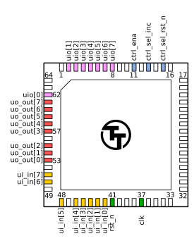
| Index | Input | Output | Bidirectional |
|---|---|---|---|
| 0 | ui[0] | uo[0] | uio[0] |
| 1 | ui[1] | uo[1] | uio[1] |
| 2 | ui[2] | uo[2] | uio[2] |
| 3 | ui[3] | uo[3] | uio[3] |
| 4 | ui[4] | uo[4] | uio[4] |
| 5 | ui[5] | uo[5] | uio[5] |
| 6 | ui[6] | uo[6] | uio[6] |
| 7 | ui[7] | uo[7] | uio[7] |
I will be targeting the widely available Microchip LAN8720A/LAN8720AI (which will be the only mention of AI in this article) PHY chip for this interface. I will be going more in-depth as to how this ASIC will be interfacing with this PHY later.
Area#
My second major constraint is my limited die area.
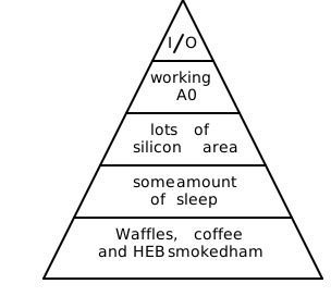
I am paying for all this out of pocket afterall, and more area means a higher manufacturing cost. Now I am not trying to accumulate a pool of gold or anything, it’s just that, in compliance with Maslow’s hierarchy of needs, waffles rank higher than area, and higher manufacturing cost means less waffles. So just like any semi-conductor company, I am incentivised to keep my area budget under control.
Because store-and-forward requires the switch to store the entire packet before forwarding it, and because ethernet frames can reach upwards of 1.5k Bytes (and 9k+ for jumbo frames), they require massive amounts of storage. A workaround for that would be to store the packet to some off-chip memory but I don’t have the pin budget to afford that right now, so on-chip memory is my only option.
The problem is, on-chip memory consumes a lot of area given the large area footprint of SRAM and the even larger area per stored bit footprint of flip-flops.
Now if we were talking of a few bytes this could be negotiable, but for multiple 1.5k Bytes packets this is a dealbreaker, thus ruling store-and-forward out.
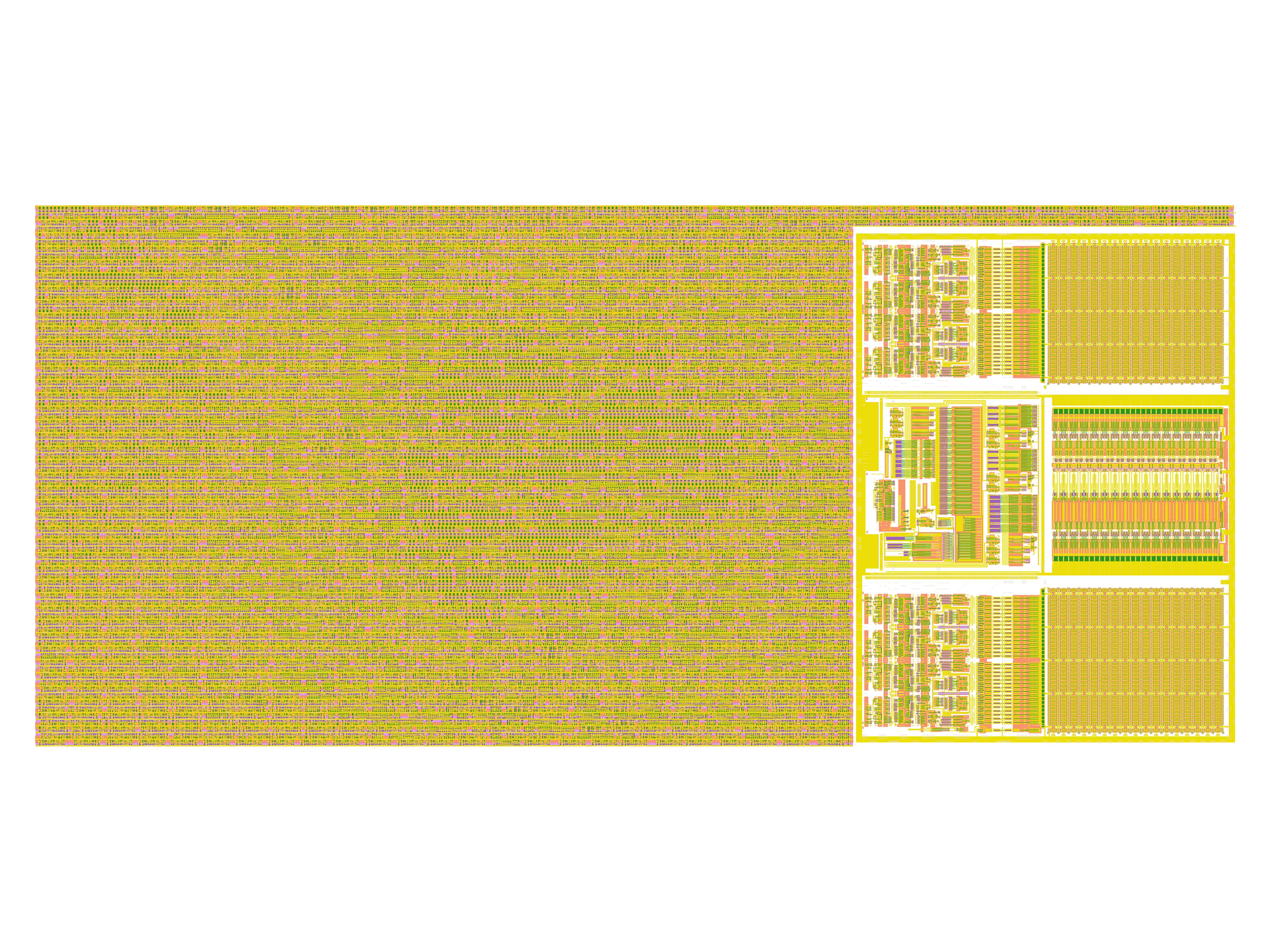
W (west) orientation.Assuming I was using Tim Edward’s excellent OCD 256x8 SRAM IP, a single 256 Byte SRAM occupies 301.3 x 224.93 um (using W orientation in this implementation) and consumes just by itself 1/3 of the floorplan. If we want to store even a single full packet we would need 6 of such instances, and since we have 3 ports, we would then need to replicate that 3 times, so 18 instances in total. Now, we have a larger 1028 Byte version of this SRAM that is 301.3 x 515.81 um which nicely increases our storage area density. But again, if we were to instantiate six such macros this would occupy x3 the area than we currently have to spare.
Now, the Tiny Tapeout shuttle chip does support me scaling up this design up at most another two factors of two, or 4x. But the cost would also scale by a factor of 4, at which point we are getting into full chip orders of magnitude of cost. And if I were to go down the full chip route, since I then have the possibility of having a lot more pins to play with, this re-unlocks the possibility of interfacing with much larger external memories, thus changing the landscape of what the correct technical tradeoff would be again.
Easy to use#
Lastly, I want something that doesn’t require external software or configuration.
Firstly because I would like external third party users in the community to be able to easily pick this ASIC up and start using it. And that becomes increasingly difficult as soon as I start involving custom software. I am aiming for something that is as close to plug and play as possible with ease of use being a measure of success.
Not to say that the community won’t be able to compile and flash my custom embedded abominations, just that their willingness to do so decreases exponentially with each extra step.
Secondly because I am once again working on a very tight schedule and that custom software support adds significant amounts of time to both the pre-tapeout and bringup workloads. (Let’s not forget we are still talking about a single person’s project here.) This would be especially true for this ethernet switch project since I would aim to be compatible with a widely adopted open source switch management software and protocol like SNMP for monitoring or SSH for monitoring and configuration.
Support for these protocols is not at the level of something I can trivially implement in hardware, especially for SSH, and the best design decision would be to offload to a CPU. So either integrate an on chip CPU on the ASIC or, build a custom interface to an external MCU and offload all these requests to it. Both options involve a significant software effort, with the on chip CPU also promising a huge design effort and even more area usage. At which point, I am approaching the planned architecture of the router rather than the first generation of the switch.
So, for both of these reasons, an unmanaged switch is the path I am taking.
What are we building?#
So to recap, I am building a:
- 3-port
- Full-duplex
- 100 Mbps bandwidth
- cut-through
- unmanaged
ethernet switch.
Now that we have figured out what we’re building, it’s time to focus on the fun part: how to build it! 🥳
System Overview#
The real Ethernet frame that is hidden from view#
Most people have actually never seen a full ethernet packet.
When you inspect Ethernet traffic on your computer via tcpdump or wireshark, you actually only see part of the Ethernet frame, with some parts missing. These parts are generally stripped out by your computer’s network interface before the packet is forwarded to the software realm, thus hiding them from user’s view.
Random IPv4 packet captured over tcpdump (tcpdump -xx -e -v 'ether proto 0x0800') :
16:36:51.298082 60:e9:aa:92:dc:7d (oui Unknown) > 5c:e9:31:1e:9d:00 (oui Unknown), ethertype IPv4 (0x0800), length 78: (tos 0x2,ECT(0), ttl 64, id 0, offset 0, flags [DF], proto UDP (17), length 64)
    superpitchu.53332 > dfw25s53-in-f9.1e100.net.https: UDP, length 36
    0x0000:  5ce9 311e 9d00 60e9 aa92 dc7d 0800 4502
    0x0010:  0040 0000 4000 4011 2b98 c0a8 0085 4a7d
    0x0020:  0369 d054 01bb 002c a93f 6fe8 5bd5 5378
    0x0030:  f4c9 ccae 477c 5083 0696 8fa4 4f62 57bf
    0x0040:  41a9 78a3 fc60 7781 2b8b 38a1 2ccd
The missing parts are:
- Preamble + SFD: Before the start of the MAC header exists a sequence of 7 bytes of an alternating bit sequence signifying that a packet is about to start, called the preamble, followed by a 1-byte marker ending in a double asserted bit sequence called the SFD (Start Frame Delimiter) signaling that the next bits are the MAC header.
- Frame Check Sequence Footer: At the end of the packet there is a 4-byte footer called the FCS (Frame Check Sequence), used to check whether the Ethernet frame’s content was corrupted during transmission. This is checked by both store-and-forward switches and by most computers’ network interface cards and these drop all frames that fail this test before the packet is forwarded.

And since, once they have been evaluated by the networking interface, both the Preamble+SFD and FCS serve no further relevant purpose, they are stripped out before the remaining packet bits are forwarded up the networking stack.
Now, since we’re going through the Microchip PHY, we won’t actually be interfacing directly with the Ethernet physical layer, as it will be abstracting away the precise 100BASE-TX PHY behavior, though the full ethernet frame will remain intact (including Preamble+SFD+FCS)
All our data transmission and reception will actually be done through the RMII bus interface.
The RMII interface#
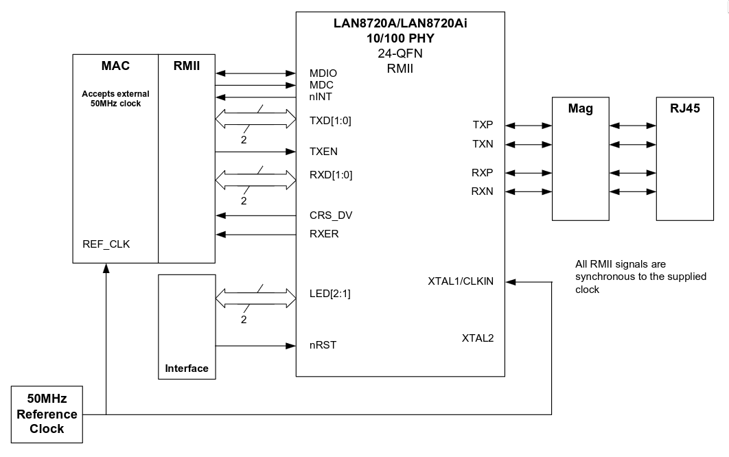
RX#
rxvvalid signal (crs_dvin the diagram above )rxererror signalrxd[1:0]two data signals
On the RX (reception) side of RMII, we have four pins: two for data, one for data validity, and one to signal that an error has occurred on the line.
Interestingly, this valid signal isn’t a pure data-valid signal but an early data-valid signal, and it’s up to our ASIC to read the incoming data and correctly identify when the Ethernet frame data actually starts using the preamble and SFD. The valid signal actually asserts asynchronously a few cycles before the start of the preamble but, deasserts synchronously with the end of the Ethernet frame.
TX#
txvvalid signal (txenin the diagram above )txd[1:0]two data signals
On the TX (transmit) side, we only have three signals: two for data and one for valid, with no error signal. This makes sense, since the error signal is there to indicate issues on the medium, and since there is no medium between the ASIC and the PHY there is no need for it in the TX direction.
Timing#
Lastly the PHY chip’s datasheet outlines the expected timings for the interface signals.
Unlike what my high level overview might have suggested, new data isn’t immediately available at the start of the clock cycle. Like in all real hardware there is an internal propagation delay. The same goes for how fast the data is allowed to transition after the start of a cycle. Because the PHY chip also contains flip-flops and is thus also subject to hold constraints, the previous cycle’s data must remain stable for a certain period of time after the clock edge before the new value can be propagated.
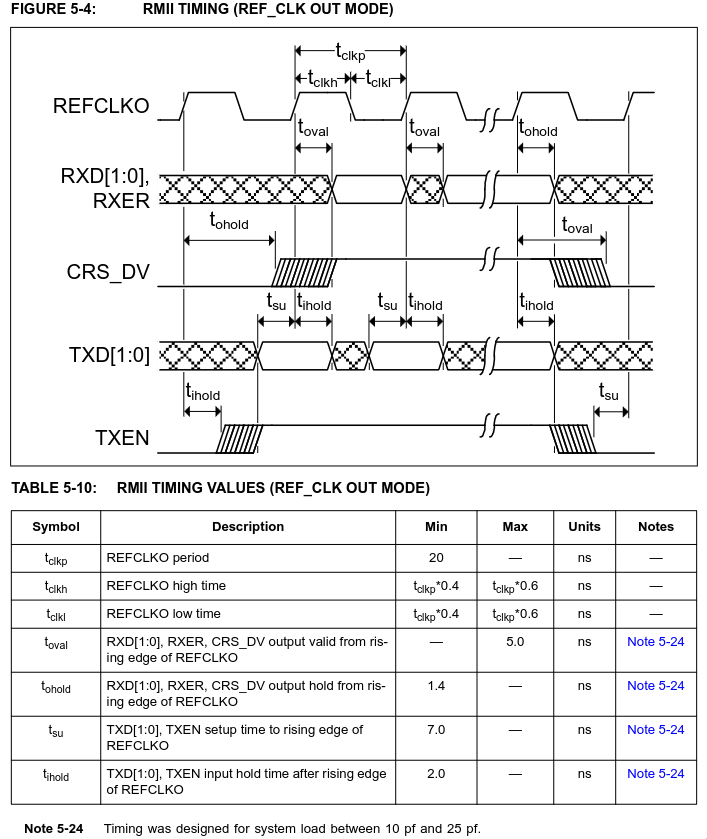
So, implementing correct signaling alone isn’t enough to properly interface with this chip. If I want my ASIC to work I also really need to make sure my physical implementation’s resulting timing respects these constraints. This is both verified and enforced by specifying design constraint rules as part of the SDC (Synopsys Design Constraints) file.
Now by designing around the constraints of the LAN8720A chip readers might be concerned that I am locking myself into a dependency on a single external chip.
And actually that is kind of the case here, I am not proud of this but I caught this discrepancy too late, and not mentioning it in this article simply doesn’t align with the technically honest recollections I am looking to do here.
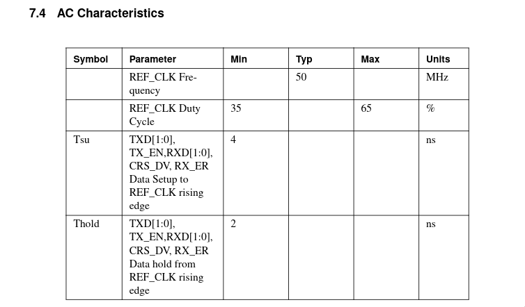
Since RMII is regented by the RMII consortium, and since in the RMII specification they include the AC characteristics I blindly assumed the LAN8720A would be compliant.
Turns out the LAN8720A isn’t actually compliant.
And, although in many cases the LAN8720’s timings are actually more constraining than the official spec, when it comes to the hold constraints on the RX pins it is actually much looser at 1.4ns less than the RMII’s consortium’s 2.0ns.
Although this might still work in practice, it would be by pure luck and I only believe in engineered luck!
Apart from that, the LAN8720A is widely available, easy to get dev boards for, well documented, and at 103 cents a piece, worth every penny.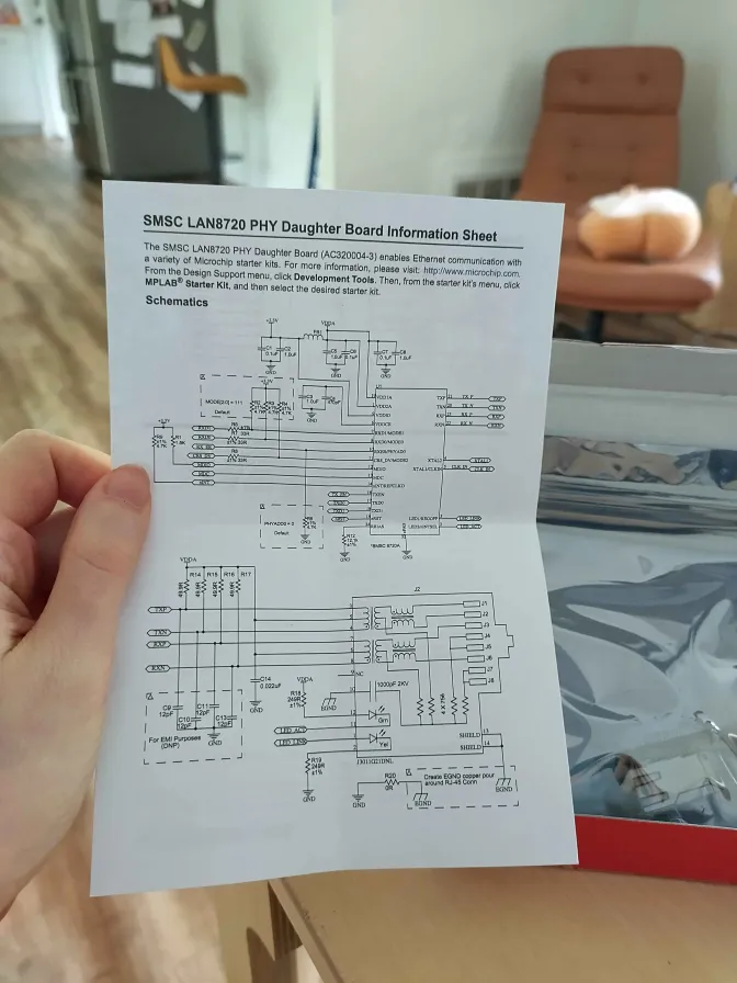
ASIC pinout#
Putting it together, here is what the final pinout of our ASIC will look like connected to all 3 PHY chips. We will be referring to these as PHY0, PHY1 and PHY2.
| Index | ui (Input) | uo (Output) | uio (Bidirectional) |
|---|---|---|---|
| 0 | phy0_rx_data[0] | phy0_tx_data[0] | phy2_rx_data[0] |
| 1 | phy0_rx_data[1] | phy0_tx_data[1] | phy2_rx_data[1] |
| 2 | phy0_rx_v | phy0_tx_v | phy2_rx_v |
| 3 | phy0_rx_err | - | phy2_rx_err |
| 4 | phy1_rx_data[0] | - | tx_phase |
| 5 | phy1_rx_data[1] | phy1_tx_data[0] | phy2_tx_data[0] |
| 6 | phy1_rx_v | phy1_tx_data[1] | phy2_tx_data[1] |
| 7 | phy1_rx_err | phy1_tx_v | phy2_tx_v |
Note: As a reminder, there are a total of 24 pins: 8 inputs, 8 outputs and 8 bidirectional pins.
Address Resolution#
At its heart, a switch is actually a conceptually simple piece of networking equipment whose role is to read and forward incoming Ethernet frames to the correct ports. Matching incoming packets destination MAC addresses to the correct port is accomplished by an internal structure called an address table.
Like a software dictionary construct, it maps a destination MAC address to a switch port index.
In order to build this correspondence, the switch reads incoming traffic’s source MACs, keeping track of which port each source MAC was seen on, in order to forward future traffic to the correct port.
Putting it together: when an incoming Ethernet frame arrives, the switch first reads the destination MAC from the frame header and checks the address table for a matching entry. If there’s a hit, it forwards the packet to the specified port. And in cases where there is no hit, in a best effort to minimize packet drops, it broadcasts the frame on all ports except the one it came from.
At least that is the high level overview, in practice, this is hardware, so things get a bit more hard (pun intended … no, I am not sorry).
Filling the table#
Recall that this switch is unmanaged, it needs to autonomously learn the correct ports corresponding to each device’s MAC address. It does this by reading the source MAC of all incoming Ethernet frames. Once it has the source MAC, it checks the address table to see if this MAC is already present. If no entry exists, it writes a new one.
The requirement that all entries in the table be unique is not only a correctness requirement but also stems from two physical implementation constraints (see ASIC implementation rules for readers not already deeply familiar with ASIC design ):
- Most efficient utilization of the table: since the table is implemented in hardware not only is its size fixed but each additional entry is non-linearly more expensive. Since this first generation 3 port design only features 4 such entries it is imperative to make the most use of each entry, and duplicated entries are a pure waste.
- Timing: lookup of this address table is on the critical path. But by guaranteeing that each hit is unique, we can replace the priority mux selecting from individual entry hit to the table hit, with a lower logic depth and/or reduction tree. See the code below as an example for the entry port hit to table port hit.
always @(*) begin
    /* verilator lint_off CASEOVERLAP */
    (* parallel_case *) // telling synthesizer it can optimize this from a priority mux to a parallel case
    casez(mac_hit) <- onehot0 entry hit vector
        4'b???1: port_hit = mem_port_q[0];
        4'b??1?: port_hit = mem_port_q[1];
        4'b?1??: port_hit = mem_port_q[2];
        4'b1???: port_hit = mem_port_q[3];
        default: port_hit = {PORT_IDX_W{1'bX}}; // port hit will only be used if we have at least one valid entry hit
    endcase
    /* verilator lint_on CASEOVERLAP */
end
So, like all hardware structures, this table has a limited, fixed size. In the best case, assuming there are multiple free entries, a static allocation algorithm is used to select which entry the new address is written to. If there is a single free entry it is used.
Where things get complicated is when there are no available entries. To explain what happens in this case, I need to take you on a quick detour and talk about Time-To-Live (TTL).
Time-To-Live 🪦#
Each entry in the table actually has three parts: the MAC address, the port, and a time-to-live counter.

So, why am I sacrificing some of my very precious on-chip storage for this counter? Well, because I must !
It implements an aging mechanism: entries in the table are only valid for as long as their TTL hasn’t expired. This is a necessary mechanism for networking equipment, to make sure old entries aren’t kept alive as it could result in improper forwarding.
Imagine the following scenario: a device is connected to our switch on port 0, but then it’s disconnected from port 0 and re-connected to port 1. If that device never transmits again, the switch has no way of being made aware that the port for this device has changed. So without an ageing mechanism, as long as the entry isn’t re-allocated, it would continue forwarding all packets destined for that device to the wrong port. Meanwhile, all traffic destined for the device would be lost.
Because of this, all switches, let they be managed (or unmanaged) implement such an ageing mechanism, where entries are regularly purged from the table. In our switch, this TTL counter also indicates whether an entry is valid (TTL != 0).
Then, at a regular interval, a hardware internal event is triggered and all the table’s TTL values in the table are decremented by 1.
This TTL is a hard-set 300 second (5 minute) invalidation cycle. All entries, if not refreshed within this five-minute window, will ultimately be invalidated.
Replacement policy#
Coming back to our write example, what happens on a write when we have no invalid entries?
For cases like this the hardware implements a replacement policy.
Firstly, in parallel to the other address table lookup mechanism, the hardware keeps track of the oldest valid entry based on the TTL. For cases where multiple entries have the same age, we once again have a static tiebreaking rule. This oldest entry is called the victim and is selected for new allocations.
Now, in my explanation so far I have suggested we had 2 distinct cases:
- At least 1 invalid entry
- No invalid entries
But in practice, since the first case is actually a generalization of the replacement policy where entries ages are 0 the replacement policy is always used for allocating new entries. The distinction is actually between allocating entirely new entries (for which the MAC address isn’t in the table) and existing entries.
Updating existing entries#
Even for cases where we detect we have an existing entry we also want to perform a write to the table for two reasons:
Firstly, it is rewritten in order to refresh its TTL counter back to the maximum value, keeping active ports entries alive.
Secondly, we also re-write the port index, to correctly handle the corner case where the device might have been connected to a different port compared to when it was originally allocated.
And with this we have ourselves an address table for our switch. 🎉
War stories#
For this ASIC design I stuck to my classic project roadmap so after having finished writing the design and it having survived torture testing simulation I moved to the last validation step which was FPGA emulation.
This last step is particularly important for devices such as these that are expected to correctly interface with third party equipment and for which the testbench might not do a proper job at capturing all the corner cases.
And, let me, dear reader, tell you a funny story that happened while I was running this emulation.
Picture this: it was an early 3am, I had finished bringing up the switch and everything was working as expected. At this point my mind was fixated on actively debating whether I should head off to bed and get a wink of sleep or toughen it out until sunrise and go directly celebrate at Waffle House. For those wondering why I didn’t just head off to Waffle House then and there: I am happily married, and intend to keep it that way.
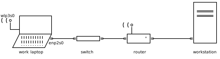
At that point my main work computer was connected via wired Ethernet to my switch, my switch to my router, and through there to my workstation.
And so there I was connected via ssh, running some physical implementation tests on my workstation, doing some small timing optimizations, when I decided that grabbing a swanky floorplan render would be a great addition to this ASIC’s documentation.
And so, I opened a GUI … (I know, who does that ?)
Thus, I was interfacing with the physical implementation tools over SSH, with visual forwarding enabled so I could see my floorplan results, and the results were unexpectedly … slow …
Like reaaaallllly slow … and laggy … and slow
I was contemplating my ssh visual lag until my two remaining brain cells reconnected and realized all my traffic was still being routed through the switch and that all the +9M packets that were composing my network traffic over the past few hours had been bottlenecked at 100 Mbps.
I was sleep deprived, your honor.
Turns out linux’s network management favors wired connections over wireless when available. So as soon as the switch became available all my ethernet traffic had stopped going over my wireless interface (wlp3s0) and was instead routed through my wired interface (enp2s0).
It turns out 100Mbps is enough for browsing reddit “the web” and Australia but not enough for ssh visual forwarding of ASIC floorplans.
At least we know one thing: it works! (Or at least, I think it works. )
The moment of truth will be around November 2026 when I get the chips back from the fab: let’s see if it stands up to being silicon proven.
The Coffee Shop family#
For those not familiar with the term, “running a home lab” is the hobby of setting up and running a small datacenter tucked between the kitchen and the bedroom. It is also, as marriage counselors can attest to, a sign that the wife is a saint and that their marriage will be fine (allegedly).
Homelab [hom-læb]: a laboratory of (usually slightly outdated) awesome in the domicile.
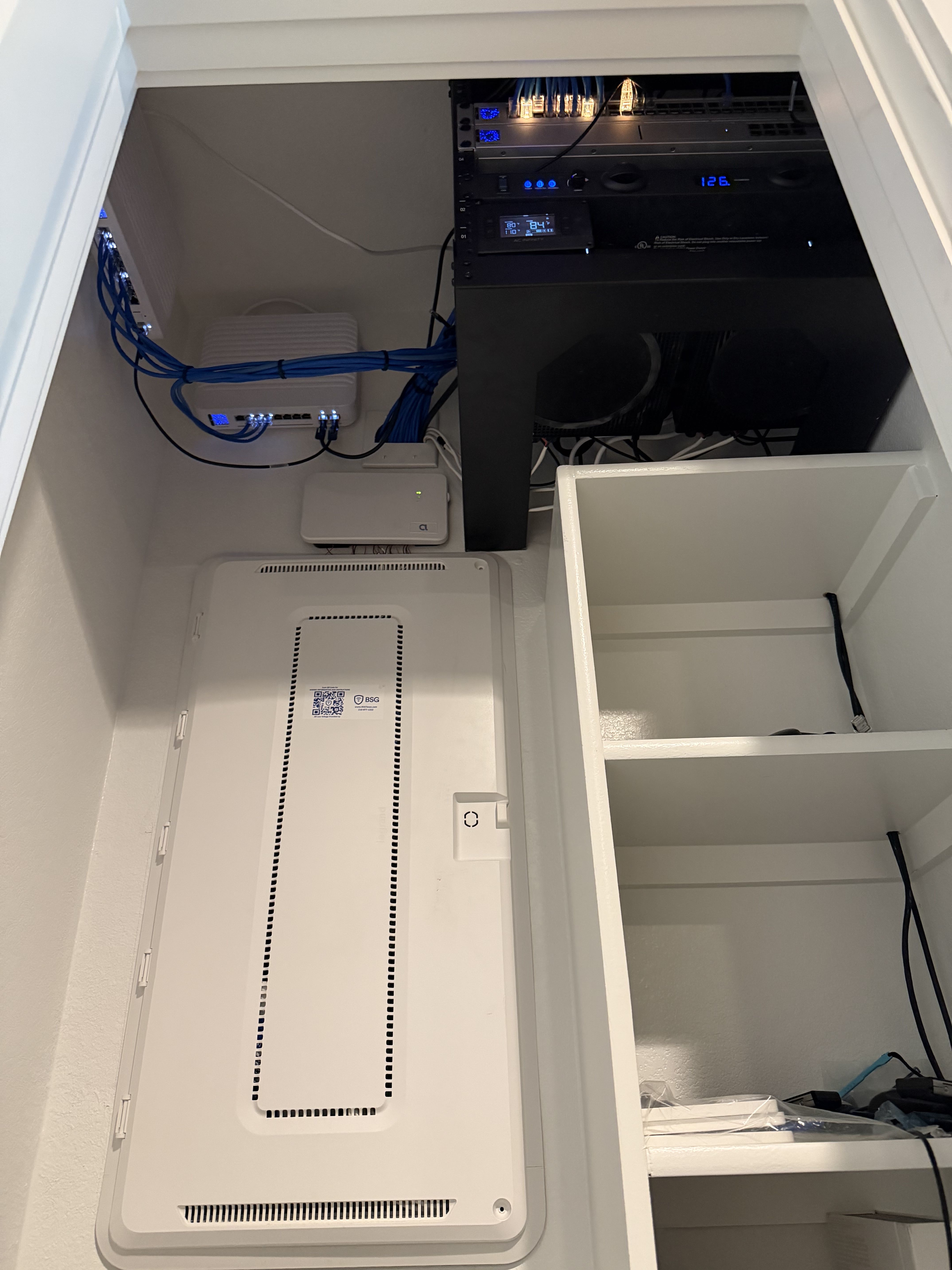
So it probably comes as no huge surprise that I have an interest in homelab’s.
But one humble switch doesn’t qualify as a homelab, no, there must be more, and it just so happens that there is.
This is actually part of a larger family of open source networking hardware IP that I have dubbed the “Coffee Shop” family.
It includes:
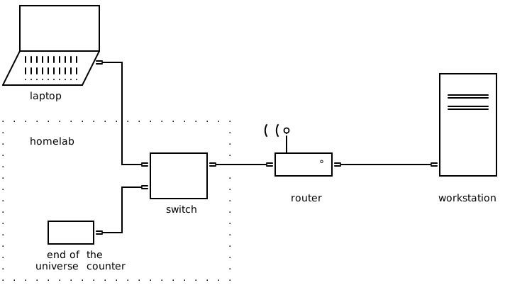
coffeepotfirst generation switch.teapotEthernet wrapper for building network connected accelerators.coldbrewEthernet connected beacon for broadcasting an ethernet frame with an uptime count until the heat death of the universe.
And,since all of the ASICs mentioned above are already taped-out, in mid November when the silicon comes back I can start building my first fully custom homelab!
What is next ?#
Obviously, the long-term plan is to replace my router, but before that, I first need to get this switch silicon proven, and then expand it with both more entries for the address resolution table and more ports. Right now, because of the Tiny Tapeout shuttle’s limitations, I can only fit three ports max. But if I move to a full chip, then I control all the pins! 🔥 w 🔥
A full chip would allow me to greatly bump my pin count to between 56 and 122 pins, giving me enough precious pins to make a much more respectable 8 ports switch chip.
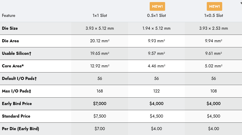
At which point, my measly four entries for the address resolution table just are not going to cut it. To address that, I can either scale the number of entries up with more pure digital logic as I am doing now, or change paradigms entirely and move to the analog realm. Because in this beautiful land lives the mystical creature known for its low lookup latency and its far superior scaling prowess that is the content-addressable memory, or CAM for short. 🌈
Although realistically I could maybe scale up the number of entries with a pure digital approach a few more orders of twos, this would require significant additional logic complexity and would stretch my tight timing even more. But if I wanted say 64 entries or more, a CAM would be the way to go.
Closing words#
So while I wait to get this first generation silicon back from the fab the next item on my TODO list is to expand my address table, potentially by building an analog content-addressable memory.
Meanwhile, some of my previous silicon has started coming back with the first-generation systolic array recently landing in my mailbox!
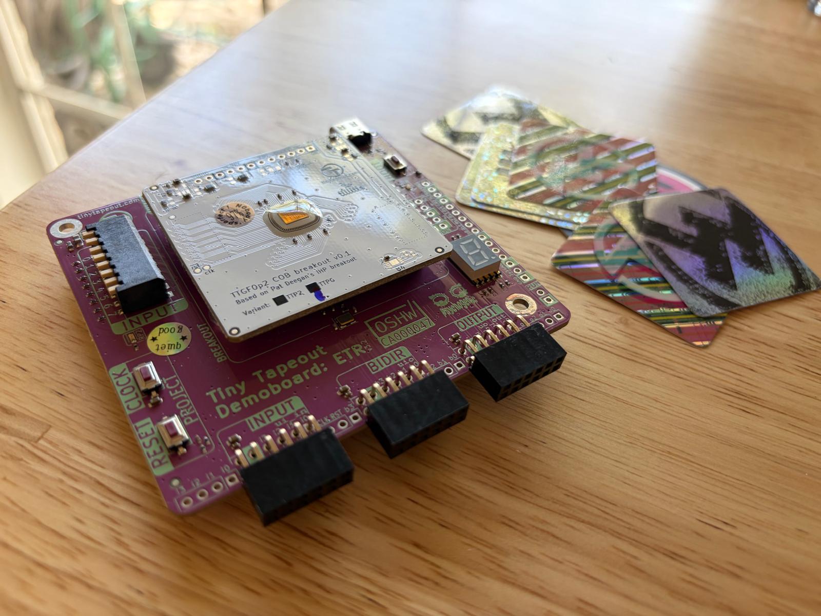
But before any of that can start, there’s one tradition I will never miss out on!

At least that is where this story was supposed to end …
Round 2#
wafer.space was started by Tim Ansell, also known as mithro online.
The open source silicon community is actually really tiny, so we were acquainted.
So, while I was wrapping up this article, amused with my own typos, I sent him a small message.
And that is where he dropped the bombshell:

Recall Maslow’s pyramid from a few paragraphs back? Well scrap that, it’s not applicable when we are talking about the possibility of FREE AREA.
Now there is just one problem: we are not talking about just a single macro but doing a full chip here. Plus, I need to scale things up to actually make good use of the additional silicon and pins and I have nothing started to that effect.
Also, tapeout is in 4 days …
Welcome to round 2!